Conception of WS2500/WS7000 sensor
(Still under construction)
Introduction
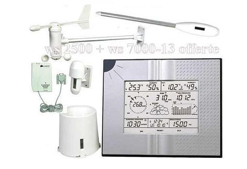
I have since now more than 10 years a weather station WS2500. A this time, it was the flagship of Lacrosse Technology and from my point of view this is the best model this compagny has done. This weather station is composed with one thermometer/hygrometer, one barometer, one anemometer, one rain gauge and one luxmeter(which is something rare). The size of the screen of this station is big. However, it can be criticized for its 3min measurement step and the wind speed measurement which is a bit "random". It has been a few years since this station is no longer manufactured and it becomes almost impossible to find replacement sensors. And I don't want to put in the carbage a station that works perfectly just because one of the sensors is broken and having to reinvest hundreds of euros in a new weather station. This is the reason why I decided to undertake the realization of a "home made" sensor. And if this project succeeds, then I could eventually troubleshoot the people who are in the same situation as me.
General description
The sensor specification is the following:
- Fully compatible with weather station W2500 and WS7000.
- One printed circuit board common for all sensors. It must be configurable in any sensor.Un seul circuit imprimé commun à tous les capteurs. Il doit être configurable en n'importe quel capteur de la WS2500/WS7000 (température, humidité, pluie, vent...etc).
- Battery operated, recharged by a solar cell. The sensor must be able to operate a dozen days without light and must have a longevity of a few years
- Minimal transmission range of 50m.
To achieve this, a microcontroller will perform the communication with different sensors. The microcontroller software will determine which type of sensor is emulated. It will at the same time ensure the transmission of information on the proper format via 433Mhz link. As a reminder, the transmission protocol for the sensors is described on this page . This sensor is also the opportunity to improve the measurement of the wind speed which as I said above is not very reliable for the WS2500. With this new sensor, we will be able to rethink the measurement of the wind speed and thus improve the reliability. By using the transmission protocol of the sensor WS7000-20 (sensor which is not managed by the weather station), it is thus possible to send an average speed, a maximum speed and a direction in the same transmission.
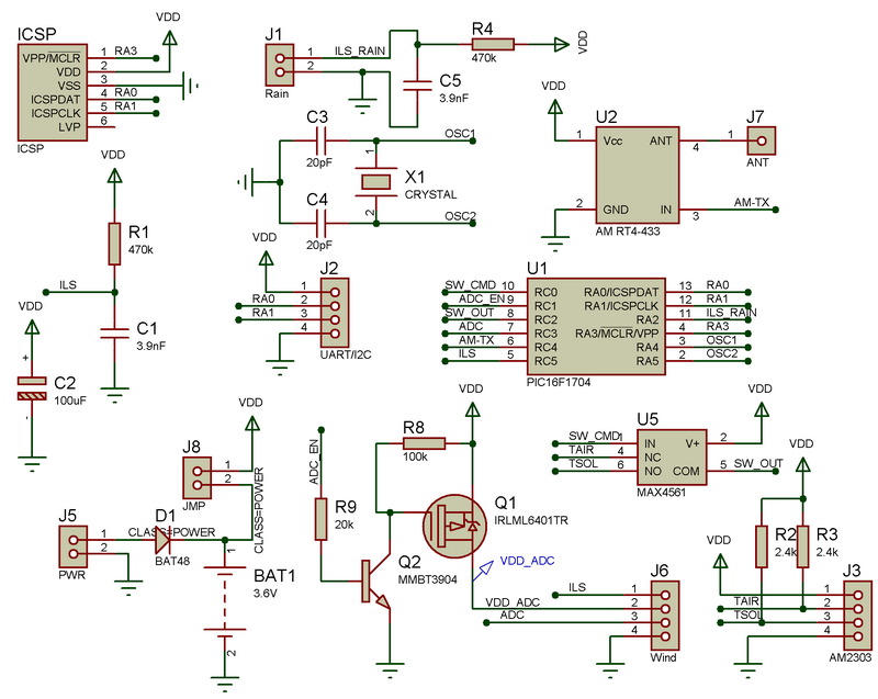
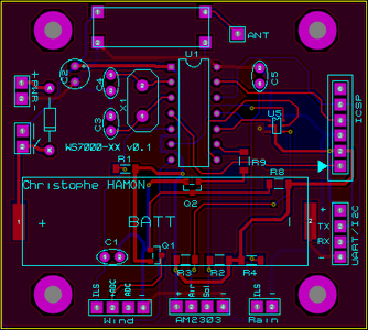
Electronique schematic
Nothing very complicated for the electronic part. We find:
- A PIC 16F1704 performing all the calculations
- A
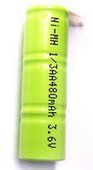
RT4-433RT14-433P module for 433Mhz data transmission - A 3.6V Nimh battery (480mAh) recharged by a solar cell of 5V, 50mA.
- A am2303 (or am2302) sensor for the measurement of temperature and humidity
- Inputs for the ILS of the anemometer and rain gauge and an analogue input for the wind direction
- An I2C bus for communication with a brightness sensor, at least...
Battery sizing
Obviously, a stand-alone installation, powered by a solar cell coupled to a NiMH battery, supposed to be several years outdoors, must have as little power consumption as possible.
The frequency of the quartz (4MHz) was chosen so that the PIC does not consume a lot (<1mA) while having correct execution performance. Thus, in the presence of all the sensors, an average consumption of the order of 1 mA is achieved. It should be noted that during the emission of the data, the consumption is increased to 5mA (due to the transmitter RT4-433) but for a very short duration (<100ms)
If you consider that it does not do beautiful every day in Bretagne :-), the assembly must be able to run at least 20 days without being recharged. What makes us a battery whose capacity must be minimum of: 20days * 24h * 1mA = 480mAh. Exactly the capacity of some battery found on the internet ...
But actually, it is the cost of the solar cell that determined the capacity of the battery. The most popular solar cells (made in China) are between 5 and 6V and are capable of delivering current up to 100mA (actually less than half the time). If you want to preserve the NiMH battery, do not charge it more than 10% of its capacity. So if we do the reverse calculation, with a cell capable of supplying a current of 50mA, we need a battery whose capacity is greater than 500mAh. The 50mA are rarely reaches or only in peak, so a battery of 480mAh will suit perfectly.
For more information on solar charging, you can consult these two very interesting links from robotroom.com:
NiMH solar charging
Winter NiMH charging
The measures
Temperature and humidity (WS7000-25)
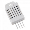
The AM2303 sensor is used to measure temperature and humidity. An AM2302 / DHT22 sensor can also be used but its accuracy is lower.
Two of these sensors can be used simultaneously to measure air and soil temperature, for example. Because we don't have enough inputs on the PIC, an analog bidirectional switch (max4561) has been added. It would have been better to take a microcontroller with more inputs / outputs because the max4561 is a very small circuit that is not evident to weld by hand. By activating a switch pin, you can choose which sensor to communicate with. According to the specification of the sensor, the length of the cable connecting it to the microcontroller can easily go up to 10 m.
Wind speed and direction (WS7000-15)
To carry out these measurements, the sensor of the WS2500 / WS7000 on which the ILS signal is fed (switch which switches each time the cup magnets pass) and the potentiometer signal which measures the direction of the wind.
The PIC comparator module (ECCP) is responsible for measuring the time between each pulse of the ILS. A measurement of the wind speed (and more particularly of the wind gusts) is thus obtained as accurate as possible. The ADC (analog and digital converter) module measures the voltage at the output of the potentiometer to deduce the direction of the wind.
The transistors setup serves to measure the voltage across the potentiometer of the wind direction only when necessary. Indeed, this potentiometer having a value of 50KOms, a permanent supply of it would cause a current leakage of approximately 70µA, ie 10% of the total consumption targeted, which is not negligible. The MOSFET-P transistor controlled by an NPN transistor activates this potentiometer as desired and then performs the measurement via the ADC of the PIC.
It should be noted that it would be quite possible to replace the anemometer of the WS2500 with that of another brand operating on the same principle (ILS + potentiometer). However, the relationship between the rotation frequency and the wind speed should be determined to be programmed into the microcontroller.
Rain sensor (WS7000-16)
Nothing very complicated for this parameter. Here again the sensor of the station is reused. The ILS signal is again picked up, which is used to increment a counter from 0 to 4095. This value is sent to the station. The INT interrupt pin of the PIC is used to trigger the increment.
Brightness (WS7000-19)
Use of the I2C MAX44009 sensor....
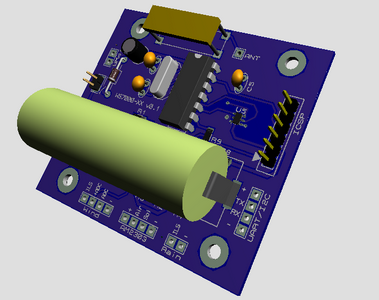
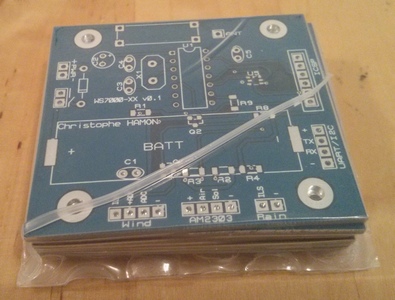
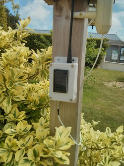
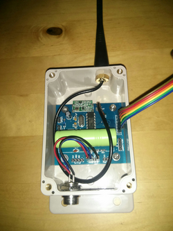
PCB realization
The circuit is designed in such a way that it can be integrated perfectly into a waterproof plastic case.
The battery will be soldered directly to the circuit.
Soldering
For a part of the components (resistors, transistors and Maxim switch), I used a new technique of welding: the soldering with the pan!
It is actually reflow soldering. Liquid tin is deposited on the pellets, the components are then placed, heated for 5 minutes in the oven while respecting a temperature curve and it is ready. Not wanting to pollute my oven, I used an old pancake pan.
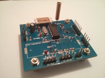
Premiers tests
Transmissions
During the initialization phase of the WS2500, the phase where the station is looking for all the sensors, the prototype was very well detected and all the sensors could be simulated. However, at the end of the initialization phase, the station no longer updated the information sent by the sensor. It took me some time to understand that the frequency of data emission is critical. Indeed, the station only activates receiver from time to time, in a lapse of time where theoretically a data transmission from one of the sensors will occur. By respecting the emission intervals for each of the emulated sensors, the transmission is carried out correctly. These transmission intervals are indicated on thesensors description page.
Consumption
To measure the consumption of the circuit, a small resistance is input, the value of which is known precisely, and then the voltage at its terminals is measured. It is thus possible to deduce the current flowing through it, corresponding to the current consumed by the prototype.
Idle: 380µA - Transmitting: ~5mA
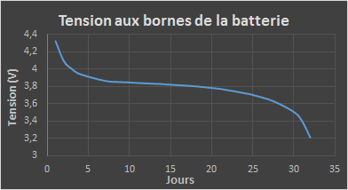
If we consider an average duration of emission + dialogue with the sensors of about 2s, an average consumption of <400µA is obtained, ie a theoretical operating time (with a 480mAh battery) of 480/0.4 = 1200h = 50 days.
In reality, the operating autonomy obtained when the battery is fully charged is about 32 days. The chart on the right shows the evolution of the battery voltage over days (indoor test at an average temperature of 20 °C). Obviously it will be necessary to proceed the same test outdoors.
Real tests
Transission range
One of the first tests was to measure the transmission range of the sensor. Test which proved inconclusive since we did not exceed 15m. To remedy to this I changed the transmitter RT4-433 by the higher model, the RT14-433P. Luckily it is pin to pin compatible, so I did not have to redo the electronic card. The change of this transmitter allowed to increase the transmission range. An antenna 433 Mhz of good quality was added by the same time.
Future developments
Temperature / Humidity
The accuracy of the am2320 sensor is not really good. A modification to be made later will be the use of the temperature / humidity sensor SHT25, a new sensor manufactured by sensirion in replacement of the SHT15. This sensor communicates in I2C, bus present on the card.
Last update : 20/07/17